To start with I decided to run rear brakes only on the buggy. Without front drive, adding front brakes is a major complication that I may add in the future.
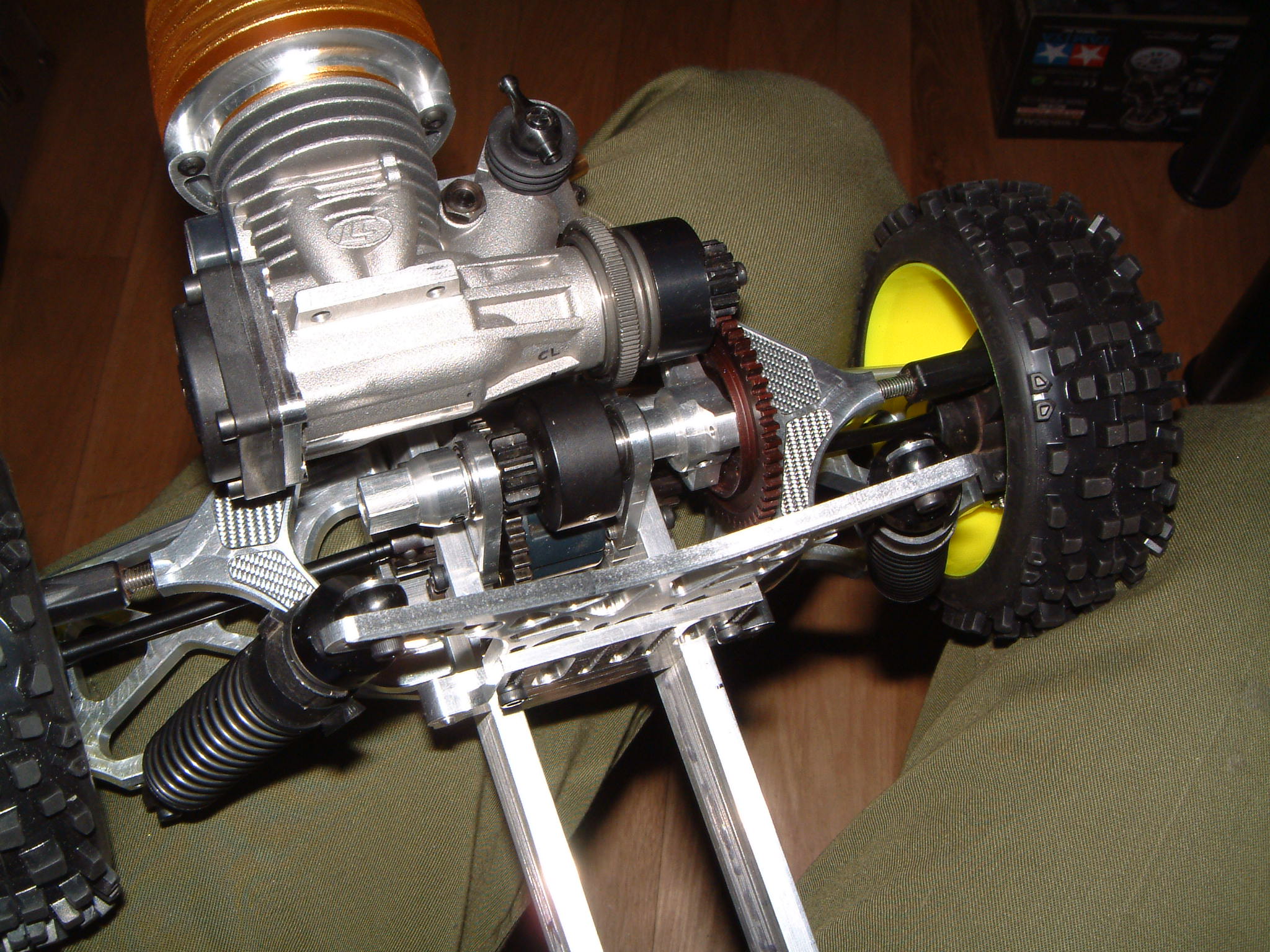
The second major decision was that it would be a transmission brake. My 1/5th scale buggy ran 4-wheel independent brakes and these were not very effective. One reason is that you need more pad force for a wheel brake than you do for a transmission brake, as the braking torque is multiplied by the transmission ratio. Of course, the driveshafts have to be able to withstand these torques if you go with a transmission brake, but that's not a problem at 1/8th scale. I realised I would need two discs mounted on the layshaft if I was to get really high stopping power, because I could only run tiny 22mm diameter discs. Anything bigger would hit the engine. Running two discs in parallel at a small diameter does give a low rotational moment of inertia which is a good thing, but not something I am greatly concerned with.
To cope with varying conditions having two different brake materials seemed like a good idea, so one disc was made in aluminium and the other in an extremely hard and wear resistant ceramic. I work with this material for a living so I fortunately have a lot of experience in this field. I don't know how it will perform as a braking surface but it is certainly worth a try, I believe true monolithic ceramic disc brakes have not been done before in RC.
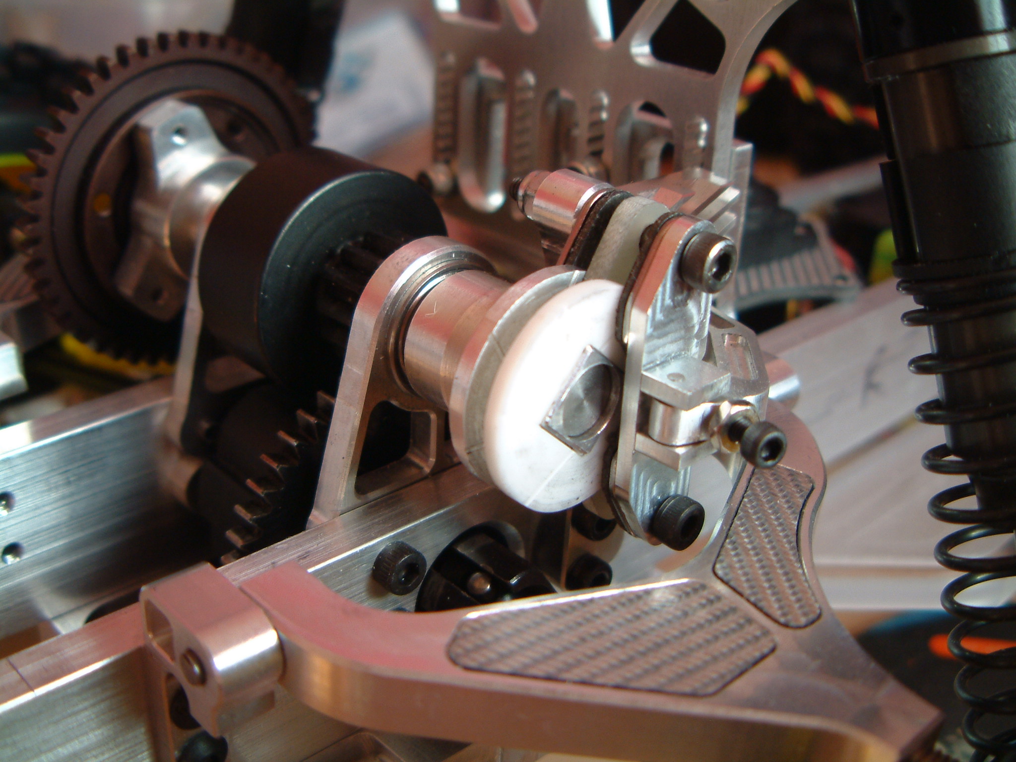
With the discs on I have to find a way to wrap a caliper around them. These carry steel shoes with pads you can buy for any commercial buggy. I used pads from a Hyper 7. There is a central separator pad machined from GRP sheet which I have found in the past to work very well with aluminium discs. The caliper body itself is heavily finned to get rid of heat, especially considering the discs are less than 1mm away from the engine! The brake is actuated by an arm with an adjustable stop to set the bite point of the brakes. The arm itself is very long and provides a very large leverage ratio. The force on the pads with the servo I am using works out to 56kg, which is obviously substantial.